TIRF alignment guide
Jump to navigation
Jump to search
Aligning TIRF lasers
Goal
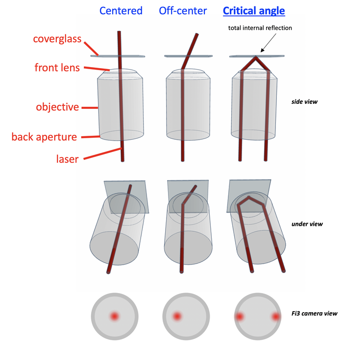
To ensure that while imaging, the laser critical angles are indeed critical, to reliably achieve total internal reflection at any desired laser rotational direction
Setting up the microscope to prepare for TIRF alignment
- Bertrand lens switch: Rotate to "B" (counterclockwise) - will need to adjust small rotatory button on this switch in a later step
- Change side switch: From Eye -> Camera (rotate) (on the right of the microscope, under the eye pieces)
- Switch Box-lights on (proximity sensor button top right of big incubator box on microscope)
- Set Observation mode Camera L (left button out of 4 round buttons, front of the microscope)
- Move Condenser down (inside black box, above sample) as low as reasonably possible (not hitting the sample...) by adjusting one of the rotary buttons on either side of condenser
Placing the sample and finding it
- Select the lens (e.g. 100X)
- Lower the lens with ESC, then hold ESC to make that the current position
- Put oil on the lens
- Center the sample holder
- Place the sample on the holder
- Switch on an illumination mode (e.g. brightfield, or epifluorescence in the software)
- Find focus on the sample (lens up, until image = sharp)
- (optional) switch-on PFS in the software to keep this focus
Performing TIRF alignment using the NIS Elements software
- Select TIRF Prime BSI mode, pick an Optical Configuration to be aligned
- Go "LiveAllCameras" and select the Fi3 view window
- Press observation mode "Eyes only" on the front of the microscope (top button, out of 4) to direct all light to the Fi3 camera
- Using the Fi3 camera window, adjust the screw on the Bertrand lens switch to focus on the incubator-box lights as good as possible
- Switch off the incubator box-lights
- Ensure the correct laser is switched on, and substantially increase its intensity setting
- Using the Fi3 camera window, adjust brightness/contrast of this view using the LUTs window, to clearly see the laser spot (if laser does not appear centered, move the TIRF angle slider in the software, and then move it back to 0)
- In the Ti2 E-TIRF Pad, hit "Align" and provide the system with the correct fully reflecting critical angle for about 5-6 different rotations (directions). The angle is correct when the laser spots look most similar and are on opposite sides of the circular objective back aperture.
- Press "compute zero from critical angles" and close window with "OK"
- (optional) move on to another Optical Configuration, and repeat steps 1-6 for that particular laser

